
maker/arduino/ RotaryEncoders
Rotary Encoders
I have a few of these – five for under a tenner.
Wiring
Wiring diagram Rotary Encoder Wiring
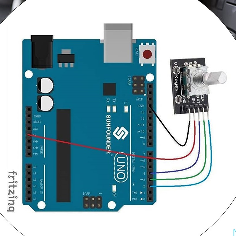
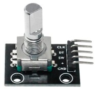
From left to right, looking down the encoder from above, with the connections below:
GND   --> GND on Arduino
VCC   --> 5V on Arduino
SW    --> (switch) to digital in
DT=B  --> (rotary B) to digital in
CLK=A --> (rotary A) to digital in
So you need two digital inputs per rotary, and one per button.
Code
I started from https://lastminuteengineers.com/rotary-encoder-arduino-tutorial/ (See below)
I wrote two classes, one for buttons and one for rotaries (as my rotaries are push ones).
By the way, mx7 is my name for a simple protocol to report things like button presses and rotary encoder movements. Bytes >= 0x80 indicate the beginning of a message, like 'rotary moved', with the remaining 7 bits specifying the type of message (which is plenty). The other bytes are <= 0x7f and are data values, so we get either 7-bit or 14-bit, or possibly 21-bit values depending on how many bytes we want to use. I'll show the usage first (for two push encoders connected to an ArduinoMega):
I intend to see how many rotaries a Mega can cope with. Two seems fine, and I'd be pleased with 8.
Rotary rotary0(0,22,23);
Rotary rotary1(1,24,25);
Button button0(0,43);
Button button1(1,42);
void setup() {
  rotary0.setup();
  rotary1.setup();
  button0.setup();
  button1.setup();
}
void loop() {
  // Read the rotary and button state
  rotary0.check();
  rotary1.check();
  button0.check();
  button1.check();

  // detect changes
  if( rotary0.delta ) {
    rotary0.mx7();
    output_mx7(rotary0.buf,rotary0.buflen);
  }
  if( rotary1.delta ) {
    rotary1.mx7();
    output_mx7(rotary1.buf,rotary1.buflen);
  }
  if( button0.changed ) {
    button0.mx7();
    output_mx7(button0.buf,button0.buflen);
  }
  if( button1.changed ) {
    button1.mx7();
    output_mx7(button1.buf,button1.buflen);
  }

  // reset changed flags
  rotary0.reset();
  rotary1.reset();
  button0.reset();
  button1.reset();

  // Put in a slight delay to help debounce the reading
  delay(1);
}
and the classes:
class Rotary {
public:
  Rotary(Byte _id, Byte _clk, Byte _dt) : id(_id), clk(_clk), dt(_dt) {
  }
  setup() {
    pinMode(clk,INPUT);
    pinMode(dt,INPUT);
    lastStateCLK = digitalRead(CLK);
    buf[0] = 0x84; // mx7 relative
    buf[1] = id;
  }
  check() {
    // Read the current state of CLK
    currentStateCLK = digitalRead(clk);

    // If last and current state of CLK are different, then pulse occurred
    // React to only 1 state change to avoid double count
    if (currentStateCLK != lastStateCLK  && currentStateCLK == 1){

      // If the DT state is different than the CLK state then
      // the encoder is rotating CCW so decrement
      if (digitalRead(dt) != currentStateCLK) {
        delta --;
      } else {
        // Encoder is rotating CW so increment
        delta ++;
      }
    }
    // Remember last CLK state
    lastStateCLK = currentStateCLK;
  }
  reset() {
    delta = 0;
 }
  mx7() {
    Byte d;
    // drop bit 6 and sign unextend to get a 7bit signed integer
    if( delta & 0x80 ) d = 0x40 | (delta & 0x3F);
    else d = delta & 0x3F;

    buf[2] = d;
  }
  const int buflen = 3;
  Byte buf[3];
  int8_t delta;
private:
  Byte id,clk, dt; // pins for rotary
  int currentStateCLK;
  int lastStateCLK;
};

class Button {
public:
  Button(Byte _id, Byte _pin) : id(_id), pin(_pin) {
    buf[0] = 0x81;
    buf[1] = id;
  }
  setup() {
    pinMode(pin, INPUT_PULLUP);
    int lastButtonState = digitalRead(pin);
  }
  reset() {
    changed = 0;
  }
  check() {
    int btnState = digitalRead(pin);

    //If we detect LOW signal, button is pressed
    if( btnState != lastButtonState ) {
      changed = 1;
    }
    pressed = btnState == LOW ? 0x7F : 0;

    lastButtonState = btnState;
  }
  mx7() {
    buf[2] = pressed;
  }
  Byte changed;
  Byte pressed;
  Byte buf[3];
  const int buflen = 3;
private:
  Byte id, pin;
  int lastButtonState;
  unsigned long lastButtonPress = 0;
};
Sample Code
From https://lastminuteengineers.com/rotary-encoder-arduino-tutorial/
// Rotary Encoder Inputs
#define CLK 2
#define DT 3
#define SW 4

int counter = 0;
int currentStateCLK;
int lastStateCLK;
String currentDir ="";
unsigned long lastButtonPress = 0;

void setup() {

    // Set encoder pins as inputs
    pinMode(CLK,INPUT);
    pinMode(DT,INPUT);
    pinMode(SW, INPUT_PULLUP);

    // Setup Serial Monitor
    Serial.begin(9600);

    // Read the initial state of CLK
    lastStateCLK = digitalRead(CLK);
}

void loop() {

    // Read the current state of CLK
    currentStateCLK = digitalRead(CLK);

    // If last and current state of CLK are different, then pulse occurred
    // React to only 1 state change to avoid double count
    if (currentStateCLK != lastStateCLK  && currentStateCLK == 1){

        // If the DT state is different than the CLK state then
        // the encoder is rotating CCW so decrement
        if (digitalRead(DT) != currentStateCLK) {
            counter --;
            currentDir ="CCW";
        } else {
            // Encoder is rotating CW so increment
            counter ++;
            currentDir ="CW";
        }

        Serial.print("Direction: ");
        Serial.print(currentDir);
        Serial.print(" | Counter: ");
        Serial.println(counter);
    }

    // Remember last CLK state
    lastStateCLK = currentStateCLK;

    // Read the button state
    int btnState = digitalRead(SW);

    //If we detect LOW signal, button is pressed
    if (btnState == LOW) {
        //if 50ms have passed since last LOW pulse, it means that the
        //button has been pressed, released and pressed again
        if (millis() - lastButtonPress > 50) {
            Serial.println("Button pressed!");
        }

        // Remember last button press event
        lastButtonPress = millis();
    }

    // Put in a slight delay to help debounce the reading
    delay(1);
}
How Many?
My next experiment, when I have time, is to see how many rotaries an ArduinoUno, or an ArduinoMega can handle. So far as signalling the PC over USB, it needs to send two or three bytes. Three bytes is conceptually simpler: one byte for a command word indicating movement of a relative rotary encoder (other command words would be used for potentiometers and buttons), one for which encoder, and one to indicate which direction, and how much, it has turned by. Whether de-bouncing is better done on the Arduino or in software on the PC, or perhaps some hybrid, remains to be seen.